True Bypass Relay with Muting : 뮤팅방식의 트루바이패스 릴레이
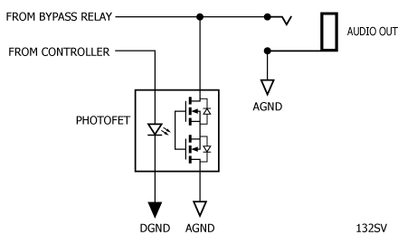
There has been discussion on Stompville here (in the comment section) and ondiystompboxes.com about problems with audio clicks when using a relay for true bypass. The consensus seems to be that the answer is to use a photofet opto-isolator to mute the audio output while the relay is switching. Two components in particular have been discussed, theToshiba TLP222G and the Fairchild H11F1M. These devices are called photofet isolators and comprise an LED (the input or control side) optically isolated from a push-pull MOSFET (the output or detector side). There is no external gate connection to the detector and the output stage is switched on by the light coming from the LED. Our intention is to use the MOSFET to short the audio signal to ground (i.e. mute the signal), then switch the relay, then release the mute. The opto isolator function allows us to separate the control signal (from our micro-controller) and the audio signal (from our bypass relay) and in particular have separate (or managed) analogue and digital grounds.
여기(댓글 섹션)의 Stompville과 ondiystompboxes.com에서 트루 바이패스용 릴레이를 사용할 때 발생하는 오디오 클릭 문제에 대한 논의가 있었습니다.
답은 릴레이가 전환되는 동안 오디오 출력을 음소거하기 위해 photofet 광절연체를 사용하는 것입니다.
특히 Toshiba TLP222G와 Fairchild H11F1M이라는 두 가지 구성 요소가 논의되었습니다.
이러한 장치는 포토펫 아이솔레이터라고 하며 푸시풀 MOSFET(출력 또는 검출기 측)에서 광학적으로 분리된 LED(입력 또는 제어 측)로 구성됩니다.
검출기에 대한 외부 게이트 연결이 없으며 LED에서 나오는 빛에 의해 출력 단계가 켜집니다.
우리의 의도는 MOSFET을 사용하여 오디오 신호를 접지로 단락(즉, 신호 음소거)한 다음 릴레이를 전환한 다음 음소거를 해제하는 것입니다.
옵토 아이솔레이터 기능을 사용하면 제어 신호(마이크로 컨트롤러에서)와 오디오 신호(바이패스 릴레이에서)를 분리할 수 있으며 특히 별도의(또는 관리되는) 아날로그 및 디지털 접지가 있습니다.

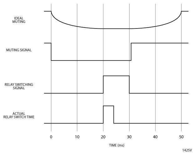
Now, we could just switch the LED on when we want to mute and this will probably work adequately in most cases. However, it would be more elegant if we could have a soft mute so the sound would fade out over a period of time (say 20 ms) then we switch the relay, then un-mute over a further 20ms, giving a total switching time of 50 ms (allowing 10 ms for the relay to change-over). To cut a long story short, the TLP222G is a better option all round than the H11F1M (more on this later), so I have been experimenting with the ’222. The following circuit has been suggested as a way of providing soft mute:
이제 음소거를 원할 때 LED를 켜면 대부분의 경우 적절하게 작동할 것입니다.
그러나 부드러운 음소거를 사용하여 일정 시간(예: 20ms) 동안 사운드가 페이드 아웃된 다음 릴레이를 전환한 다음 추가 20ms 동안 음소거를 해제하여 총 전환 시간을 제공하면 더 우아할 것입니다.
50ms(릴레이 전환에 10ms 허용). 간단히 말해서 TLP222G는 H11F1M(나중에 자세히 설명)보다 전반적으로 더 나은 옵션이므로 '222로 실험해 왔습니다.
소프트 뮤트를 제공하는 방법으로 다음 회로가 제안되었습니다.

Unfortunately, the switching characteristic of the ’222 is such that the above circuit simply delays switching of the output stage and does not provide a soft muting function. Another possible option would be to use PWM control of the LED current:
안타깝게도 ’222의 스위칭 특성은 위의 회로가 단순히 출력단의 스위칭을 지연시키고 소프트 뮤팅 기능을 제공하지 않는 것과 같습니다.
또 다른 가능한 옵션은 LED 전류의 PWM 제어를 사용하는 것입니다.

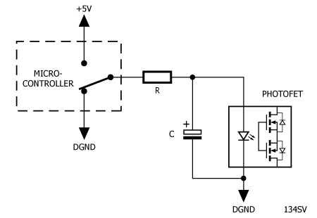
Unfortunately, the switching characteristic of the ’222 does not lend itself to this solution because the maximum useable PWM frequency for the ’222 is less than 5kHz (which is, of course, audible). We would need a PWM frequency of 40kHz or higher to make this circuit useable. However, if we hard-switch the LED (i.e. don’t use PWM), but make the resistor R fairly large, we can at least ramp the audio down:
안타깝게도 ’222의 스위칭 특성은 ’222에 사용할 수 있는 최대 PWM 주파수가 5kHz 미만(물론 들을 수 있음)이기 때문에 이 솔루션에 적합하지 않습니다.
이 회로를 사용하려면 40kHz 이상의 PWM 주파수가 필요합니다.
그러나 LED를 강제로 전환하지만(즉, PWM을 사용하지 않음) 저항 R을 상당히 크게 만들면 최소한 오디오를 낮출 수 있습니다.

Here’s a timing diagram for the above with an LED current (set by R) of about 2mA:
다음은 약 2mA의 LED 전류(R로 설정)가 있는 위의 타이밍 다이어그램입니다.

However, there is a caveat here as well. I bought a batch of 25 TLP222G’s and after trying only about half a dozen of them it became clear that the resistor required to give the 20 ms mute period is a moveable feast and would need to be selected for the individual sample of TLP222G you have – which is OK if you have an oscilloscope handy. So, it seems the way forward is to forget trying to force a soft mute of the photofet for the time being – I will continue to tinker with any ideas which come to mind. We should set the value of Rlow enough to make sure that any sample of the TLP222G will fire reliably. That value would coincide with a If of 3mA and the resistance would be (5V – 1.15V)/3mA = 1.28k so 1.5k would be adequate. This gives us our timings as follows:
그러나 여기에도 주의 사항이 있습니다.
저는 25개의 TLP222G 배치를 구입했고 그 중 6개 정도만 시도한 후에 20ms 음소거 기간을 제공하는 데 필요한 저항이 움직일 수 있는 잔치이며 가지고 있는 TLP222G의 개별 샘플에 대해 선택해야 한다는 것이 분명해졌습니다.
오실로스코프가 있으면 괜찮습니다.
따라서 앞으로의 방법은 당분간 photofet의 부드러운 음소거를 강제로 시도하는 것을 잊는 것 같습니다.
계속해서 떠오르는 아이디어를 수정하겠습니다.
TLP222G의 모든 샘플이 안정적으로 실행될 수 있도록 Rlow의 값을 충분히 설정해야 합니다.
이 값은 3mA의 If와 일치하고 저항은 (5V – 1.15V)/3mA = 1.28k이므로 1.5k가 적절합니다.
이것은 우리에게 다음과 같은 타이밍을 제공합니다.


Note that if you want to muck about with the soft mute, I have left a 20 ms delay before operating the relay. R2 will need to be in the region of 3.6k – 5.6k. You might consider a 1.5k resistor with a 5k preset in series. As previously noted, U1 could be LP2950-5V to save battery life; U2 could be ATtiny13 in lieu of ATtiny13A; and finally, U3 could be TLP222A. R1 may need to be reduced if your LED is too dim. Here’s a link to firmware hex file with timings as per figure 142SV above. No fuse changes required. TLP222G’s are available for sale in the Stompville Shop.
소프트 음소거를 사용하려는 경우 릴레이를 작동하기 전에 20ms 지연을 남겼습니다.
R2는 3.6k – 5.6k 영역에 있어야 합니다.
직렬로 연결된 5k 사전 설정이 있는 1.5k 저항을 고려할 수 있습니다.
앞서 언급했듯이 U1은 배터리 수명을 절약하기 위해 LP2950-5V일 수 있습니다.
U2는 ATtiny13A 대신 ATtiny13이 될 수 있습니다. 마지막으로 U3는 TLP222A가 될 수 있습니다.
LED가 너무 어두우면 R1을 줄여야 할 수도 있습니다.
다음은 위의 그림 142SV에 따른 타이밍이 포함된 펌웨어 16진수 파일 링크입니다.
퓨즈 교체가 필요하지 않습니다.
TLP222G는 Stompville Shop에서 판매 중입니다.
Update – Where should the Capacitor go?
I’ve received a few comments suggesting that the electrolytic capacitor should go before the resistor and this will make all the difference. In fact it makes no difference. We can’t escape from two facts we have discovered:
- The photofet has sharp turn-on and turn-off characteristics
- The actual characteristics vary significantly from sample to sample
This means that it is not practical to finesse the soft-muting function using a simple RC network. Here are schematics and timing diagrams for the three possible scenarios:
업데이트 – 커패시터는 어디로 가야 합니까?
나는 전해 커패시터가 저항기보다 먼저 와야 하며 이것이 모든 차이를 만들 것이라고 제안하는 몇 가지 의견을 받았습니다.
사실 별 차이가 없습니다.
우리는 우리가 발견한 두 가지 사실에서 벗어날 수 없습니다.
- photofet은 날카로운 켜짐 및 꺼짐 특성을 가지고 있습니다.
- 실제 특성은 샘플마다 크게 다릅니다.
즉, 간단한 RC 네트워크를 사용하여 소프트 뮤팅 기능을 미세 조정하는 것은 실용적이지 않습니다.
다음은 세 가지 가능한 시나리오에 대한 회로도 및 타이밍 다이어그램입니다.

We can see from the timing diagrams that the addition of the capacitor has some effect on the ‘mute-on’ function, but no effect on the ‘mute-off’ function.
커패시터 추가가 '음소거 켜짐' 기능에 어느 정도 영향을 미치지만 '음소거 꺼짐' 기능에는 영향이 없음을 타이밍 다이어그램에서 볼 수 있습니다.
Appendix – Choosing a Photofet (부록 – Photofet 선택 )
The Toshiba TLP222 comes in two variants, the TLP222A and the TLP222G. The two significant differences which apply here are the on-state resistance of the output (Ron) and the off-state capacitance of the output (Coff). Here is a summary of the differences:
Toshiba TLP222는 TLP222A와 TLP222G의 두 가지 변형으로 제공됩니다.
여기에 적용되는 두 가지 중요한 차이점은 출력의 온 상태 저항(Ron)과 출력의 오프 상태 커패시턴스(Coff)입니다.
차이점을 요약하면 다음과 같습니다.

Notionally, we want the lowest possible Ron (to give optimal muting) and the lowest possibleCoff (to give minimal filtering of the audio signal). However, in this case, lower Coff trumps lower Ron and TLP222G is the better choice (but it may not make much difference in practice). The Fairchild alternative also comes in two variations, the H11F1M and the H11F3M. The datasheet also refers to the H11F2M, but this is an obsolete part. Here is a summary of the relevant differences:
개념적으로 우리는 가능한 가장 낮은 Ron(최적의 음소거를 제공하기 위해)과 가장 낮은 Coff(오디오 신호의 필터링을 최소화하기 위해)를 원합니다.
그러나 이 경우 Coff가 낮을수록 Ron이 낮고 TLP222G가 더 나은 선택입니다(하지만 실제로는 큰 차이가 없을 수 있음).
페어차일드 대안은 H11F1M과 H11F3M의 두 가지 변형으로도 제공됩니다.
데이터시트도 H11F2M을 언급하지만 이것은 구식 부품입니다.
관련 차이점을 요약하면 다음과 같습니다.

Note that Coff is comparable with the TLP222G, but Ron is much higher. Clearly, we would want to choose the ‘F1 variant over the ‘F3 variant.
off는 TLP222G와 비슷하지만 Ron이 훨씬 높습니다. 분명히 우리는 'F3 변형보다 'F1 변형을 선택하고 싶을 것입니다.

So, it turns out that the Toshiba part is a better choice all round. Given that both parts have acceptably low capacitance, the TLP222G has lower on resistance, comes in a smaller package and is less expensive than the H11F1M.
따라서 모든 면에서 Toshiba 부품이 더 나은 선택임이 밝혀졌습니다.
두 부품 모두 수용할 수 있을 만큼 낮은 정전 용량을 제공하므로 TLP222G는 온 저항이 더 낮고 더 작은 패키지로 제공되며 H11F1M보다 저렴합니다.
'이펙트 페달' 카테고리의 다른 글
| BOSS OD-1 빈티지 클론 : ODYSSEY 1 오버드라이브 제작 리포트 #2 (2) | 2023.02.23 |
|---|---|
| BOSS OD-1 빈티지 클론 : ODYSSEY 1 오버드라이브 제작 리포트 #1 (113) | 2023.02.23 |
| 10 Favourite Effects Pedals of 2022~2022년 최애 이펙트 페달 10선 (순서는 랜덤)~from Music Radar (0) | 2023.01.04 |
| Arbiter Fuzz Face 퍼즈페이스 ~ Fuzz 페달의 레전드 (0) | 2023.01.02 |
| MAXON OD808 & OD-9 vs IBANEZ TS9 튜브 스크리머(Tube Screamer) 맞대결 (2) | 2022.12.21 |


